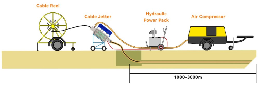
Before the cable placing operation begins, the microduct system should be checked to be assured the cable’s minimum bend radius is not violated during handling, feeding, placing, and final positioning. The equipment and all pressure fittings should be checked. The placing engine should be checked to confirm that the tension and compression limits matching the cable being placed have been properly and accurately set. Radios should be checked to confirm that all manned positions along the right-of-way are in communications and prepared to start the placement. FIG1 shows a typical unassisted microduct cable jetting operation.

FIG1 – Cable Jetting Schematic Showing Placement Without Intermediate Assist
All transitions into and out of manholes shall be direct and smooth, not violating any of the cable’s mechanical or geometrical limits.
Air pressures and hydraulic pressures shall be set according to the placing engine manufacturer’s instructions. The operation of the placing engine during placement shall follow its manufacturer’s instructions.
The placing operation shall begin slowly and continue at the slow speed until it is clear that the placing operation is progressing smoothly. The placing speed can be increased gradually until the operation reaches a fast, but completely under control speed. Speeds from 30 to 60m/min (100-190 ft/min) or more can be reached depending upon the experience of the crew and the geometry of the placing route. FEIBOER and the placing engine manufacturer recommend that the placing operation be performed at a safe and controllable speed.
Bidirectional Figure-8 Procedure
A placing plan listing the pulling locations, intermediate assist, and figure-8 locations should be developed during a pre-survey of the placing project. The placing plan will indicate the cable length to be coiled at the “figure-8” point.
For bidirectional placing operations a convenient intermediate point is selected for the figure-8 location. It should be near mid-span and, if possible, the duct section in both directions out from the figure-8 manhole should be placeable in a single operation.
Cable is jetted toward the intermediate figure-8 manhole following the jetting procedure outlined above. All cable is pulled off the reel with the excess cable figure-8 in a coil about 10 meters long at the intermediate figure-8 manhole. The figure-8 of the cable shall be done carefully, in a safe location free from access by the public.
Sufficient cable shall be left in the initial cable feed manhole to complete the splice to its neighboring cable and to provide cable slack for future maintenance operations.
After all cable has been pulled off reel and the excess cable figure-8, the pulling engine shall be moved to the figure-8 manhole and set up to complete the cable jetting operation from the figure-8 coil at the intermediate figure-8 manhole.
The figure -8 coil must be carefully turned over (“flipped”) so that the cable that was on the bottom is now on top. This cable coil “flip” will enable cable to be fed off the top of the coil to the far manhole to complete the placing operation.
Also special accessories are available for figure-8 handling which could reduce the number of manpower and total installation time.
The final segment of microduct will be jetted from the figure-8 manhole to the far end manhole. The jetting operation shall be conducted as described above. As always, the encasing conduit, sub-duct, innerduct, or microduct must be lubricated prior to the start of any placing operation following the lubrication schedule. Once the placing operation begins, lubrication must continue to be applied to the cable being jetted as it is placed.

FIG2-Bidirectional Figure-8 Procedure
Intermediate Assist
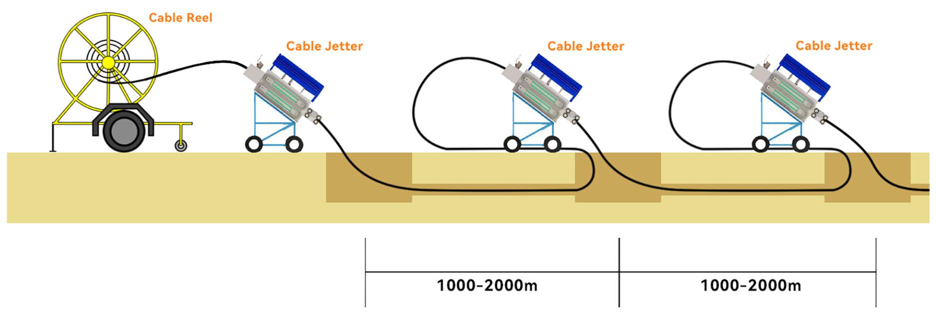
A placing plan determining pulling locations, including the intermediate assist location should be developed during a pre-survey of the placing project. FIG3 shows a cable jetting operation with intermediate assist.

FIG3-Intermediate Assist
For intermediate assist placing operations, a convenient intermediate point is selected as the intermediate location. It should be near mid-span and, if possible, the duct section in both directions out from the intermediate assist manhole should be placeable in a single operation. The area around the intermediate assist location should be capable of staging the ground support equipment (air compressor and hydraulic pump)for the placing engine.
For an intermediate assist procedure to be successful, the placing engines (primary and assist engine) need to be coordinated, so compressive forces do not build up causing the cable to buckle or kink. The assist placing engine manufacturer’s instructions to operate the engine as an assist engine in tandem with other placing engines should be followed.
Once the cable has been placed, sufficient slack cable should be provided on each end of the cable route to enable the splice to be made to the adjoining cable and to store the standard amount of slack at each splice required by the end-user of the cable for maintenance operations. Also, sufficient slack must be provided in intermediate manholes to rack the micro-duct and cable along the sides of the manhole, out of the way from harm and still have sufficient slack stored to accommodate the end-users requirements.
All ducts should be plugged at the conclusion of the placing operation. If a cable has been pulled into the duct, the duct plug should be sized for both the ID of the duct and the OD of the cable.The microduct shall be left intact through intermediate manholes during placing and racking, whenever possible unless the micro-duct was removed to enable intermediate assistance or a portion of the cable is branched off the cable route being placed.
Typically, a cable coil will be placed in a manhole or hand-hole to provide extra cable in the event of network damage or extra cable for splicing fibres. In certain environments, it may be determined that cable protection for the coiled slack is required due to the threat of rodent damage.If possible, protect any slack coils with split flexible conduit and store the coil in a safe position in the manhole or hand hole.
03-21
202502-12
202509-12
202409-05
202408-16
202408-07
202408-06
202408-02
202407-30
202407-29
2024
